

Interactions
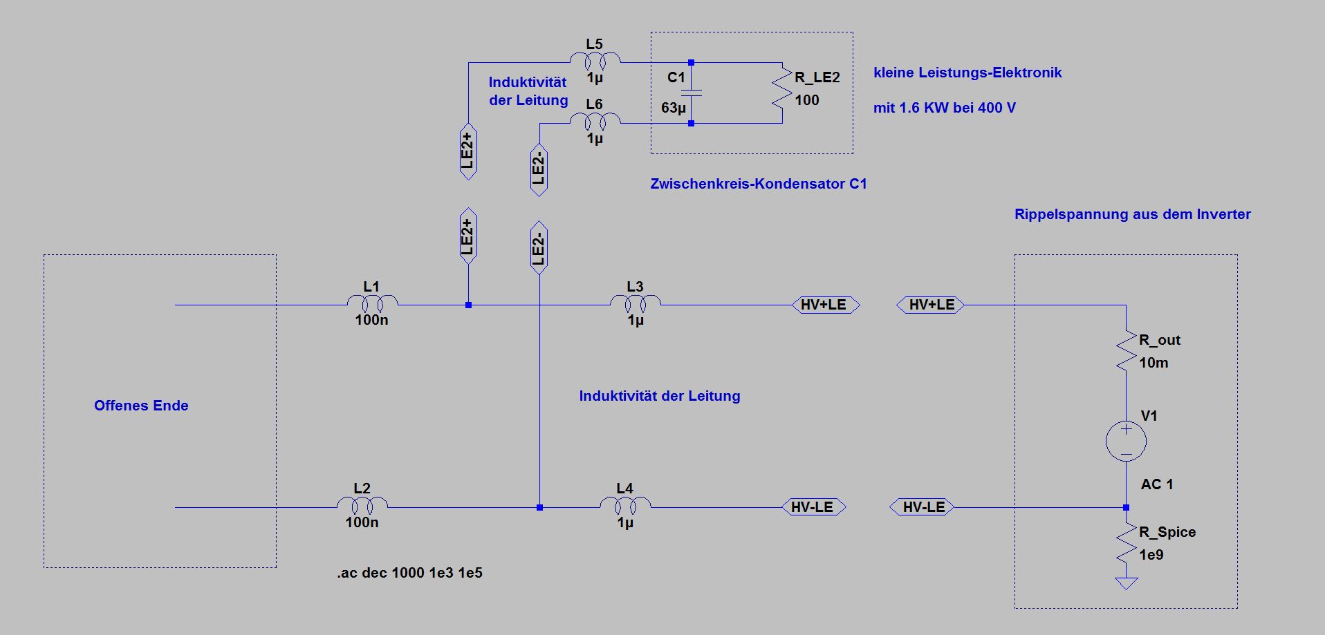
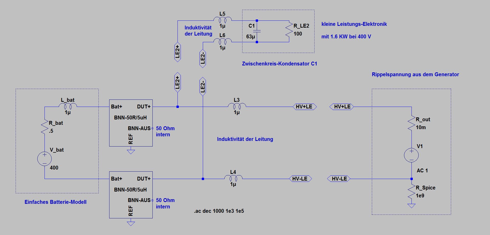
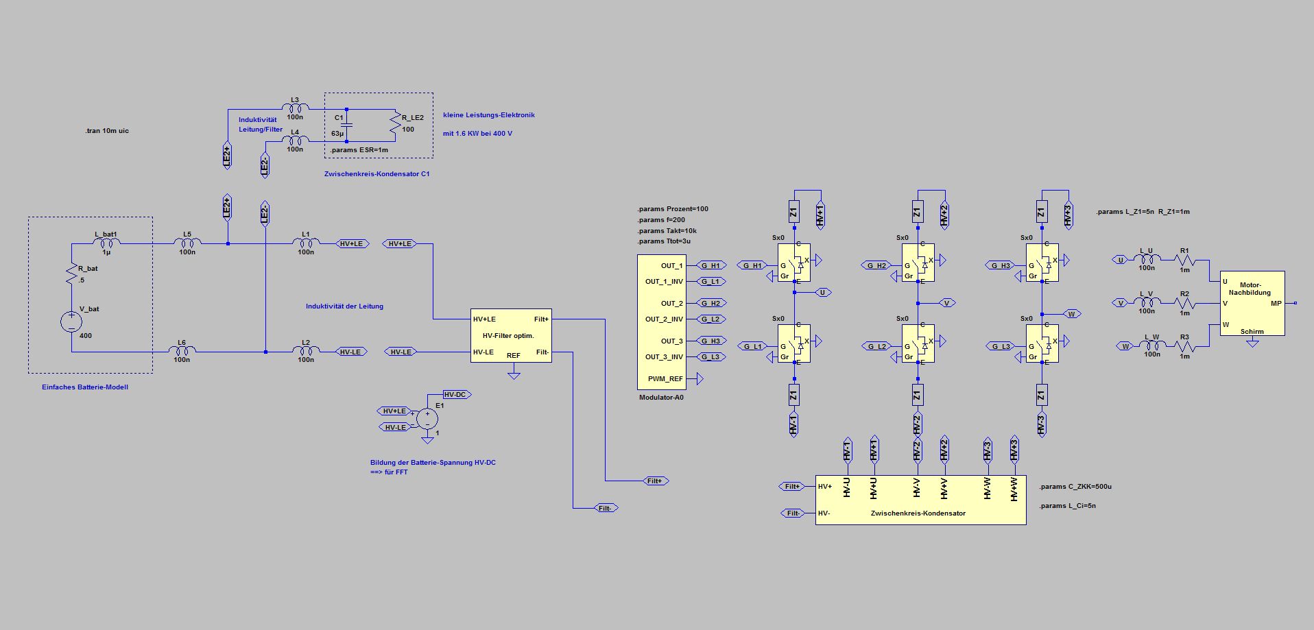
Determining the self-resonance of the DC link capacitor of the smaller power electronics LE2
The resonance frequency results from the capacitance of the capacitor C1 and the inductance of the leads L3 to L6
The voltage source on the right simulates the Ripple-Voltage from the large inverter
The internal resistance of a large inverter with respect to the generated Ripple-Voltage can be assumed to be a few milli-ohms - represented here by R_out (the connection to GND required for Spice is realized by the high-resistance R_Spice)
The power consumption of the smaller power electronics LE2 is represented by the resistor R_LE2: 100 ohm = 1.6 KW at 400 V
The battery side is initially considered as an open end
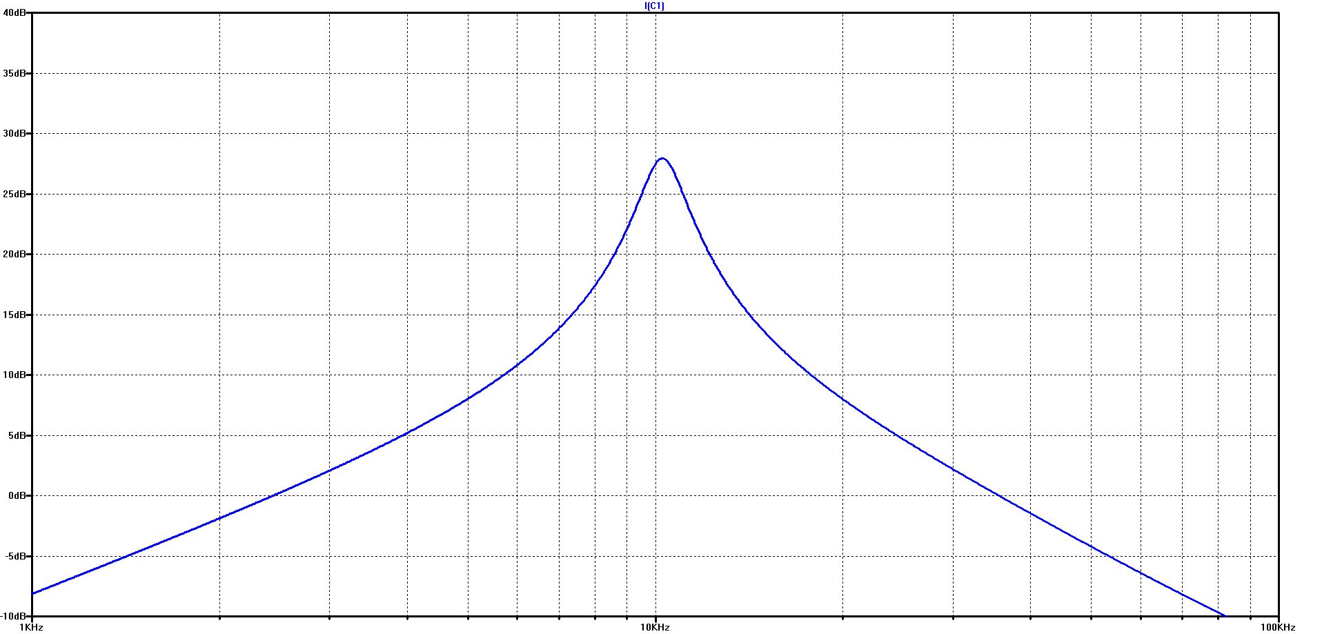
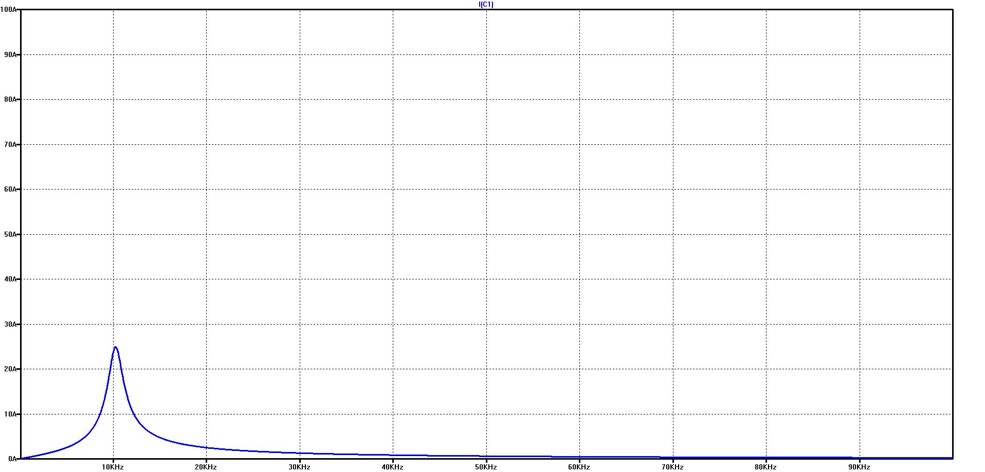
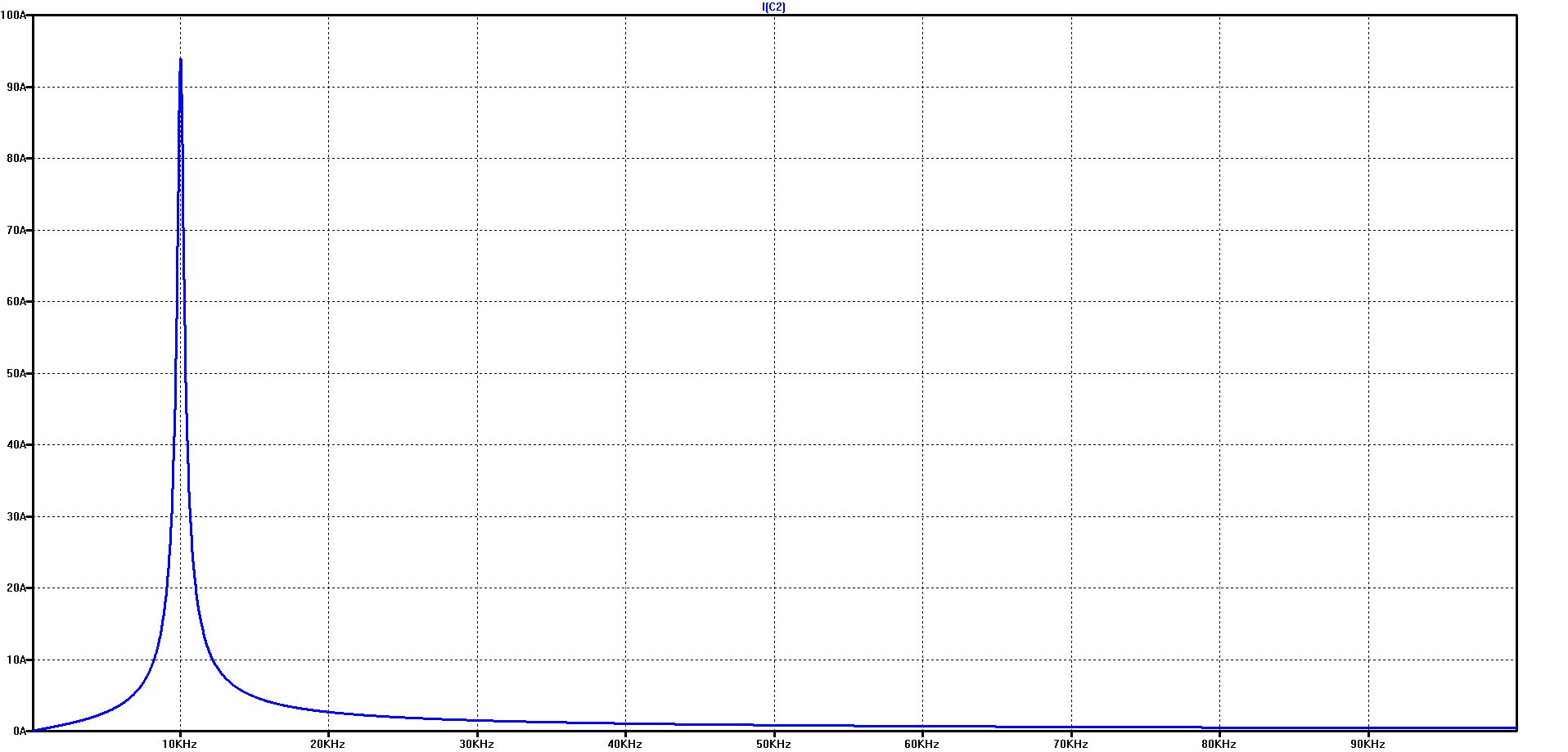
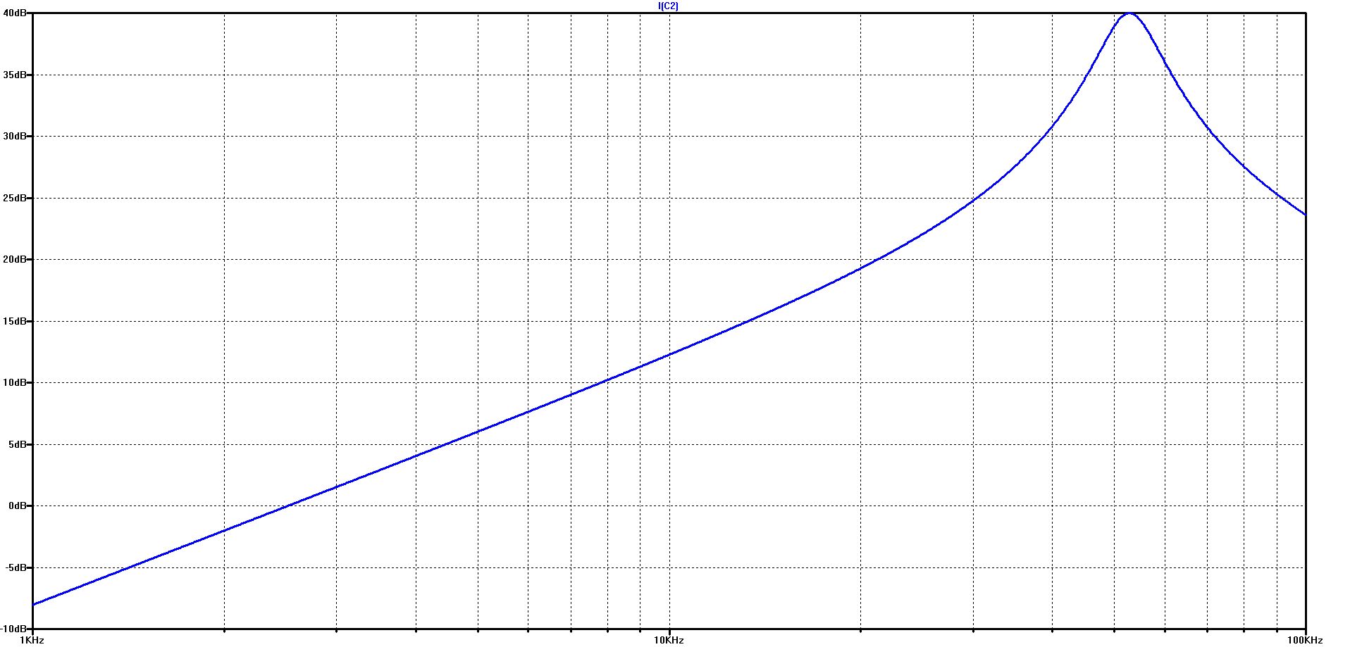
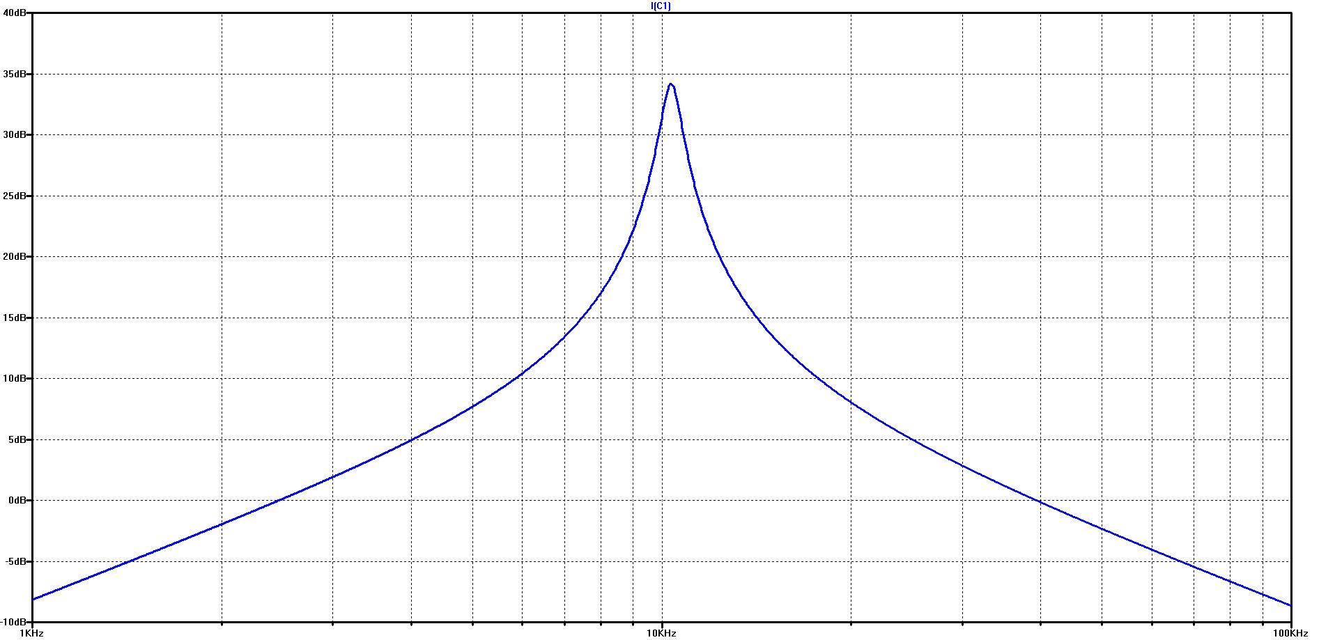
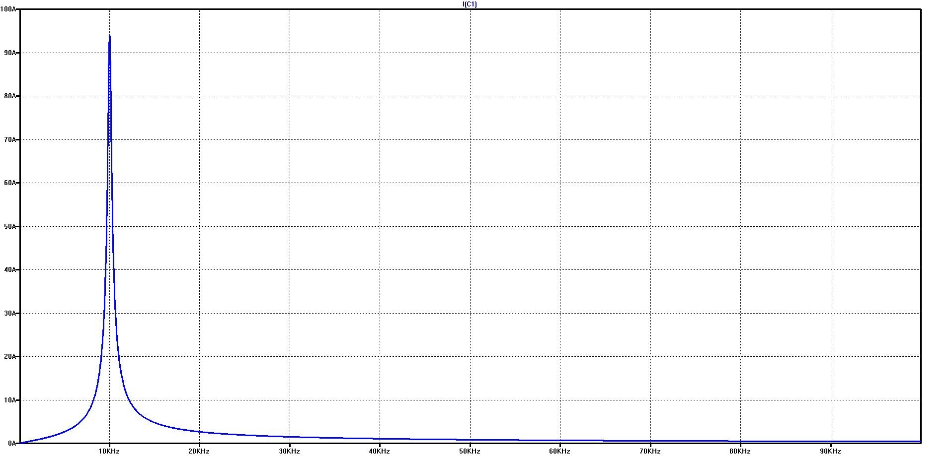
The course of the capacitor current over frequency in the logarithmic diagram on the left and in the linear diagram on the right
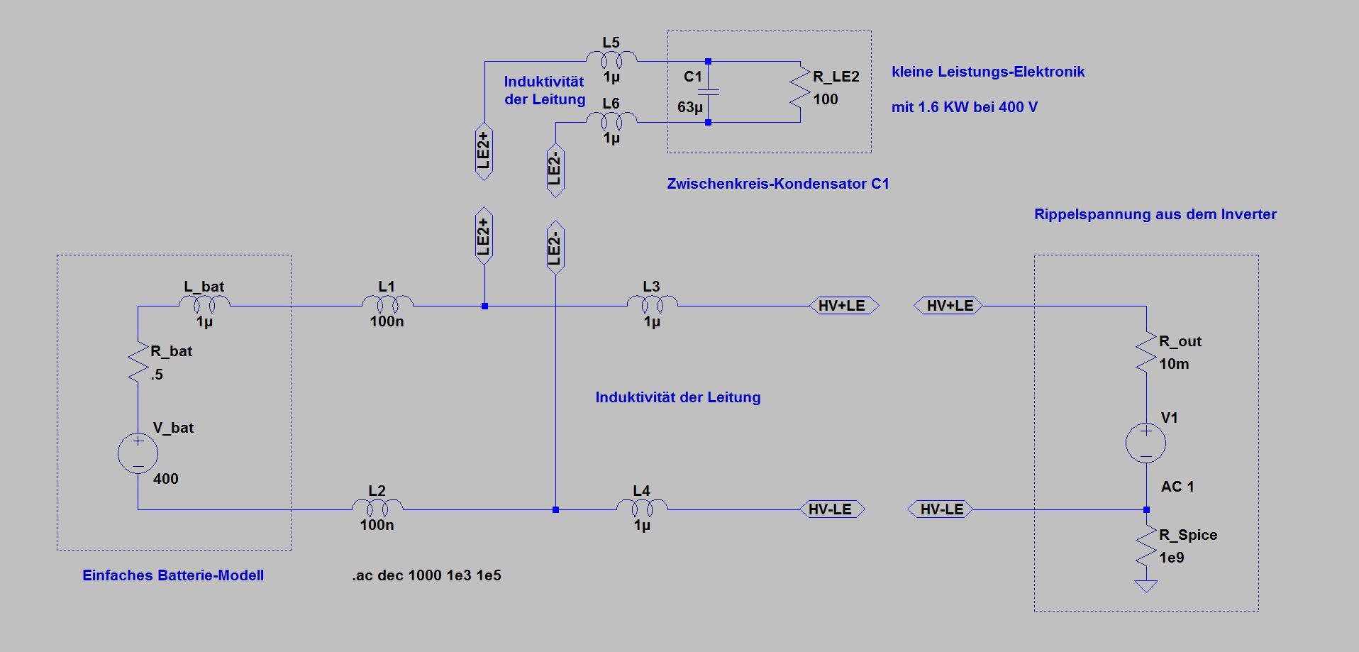
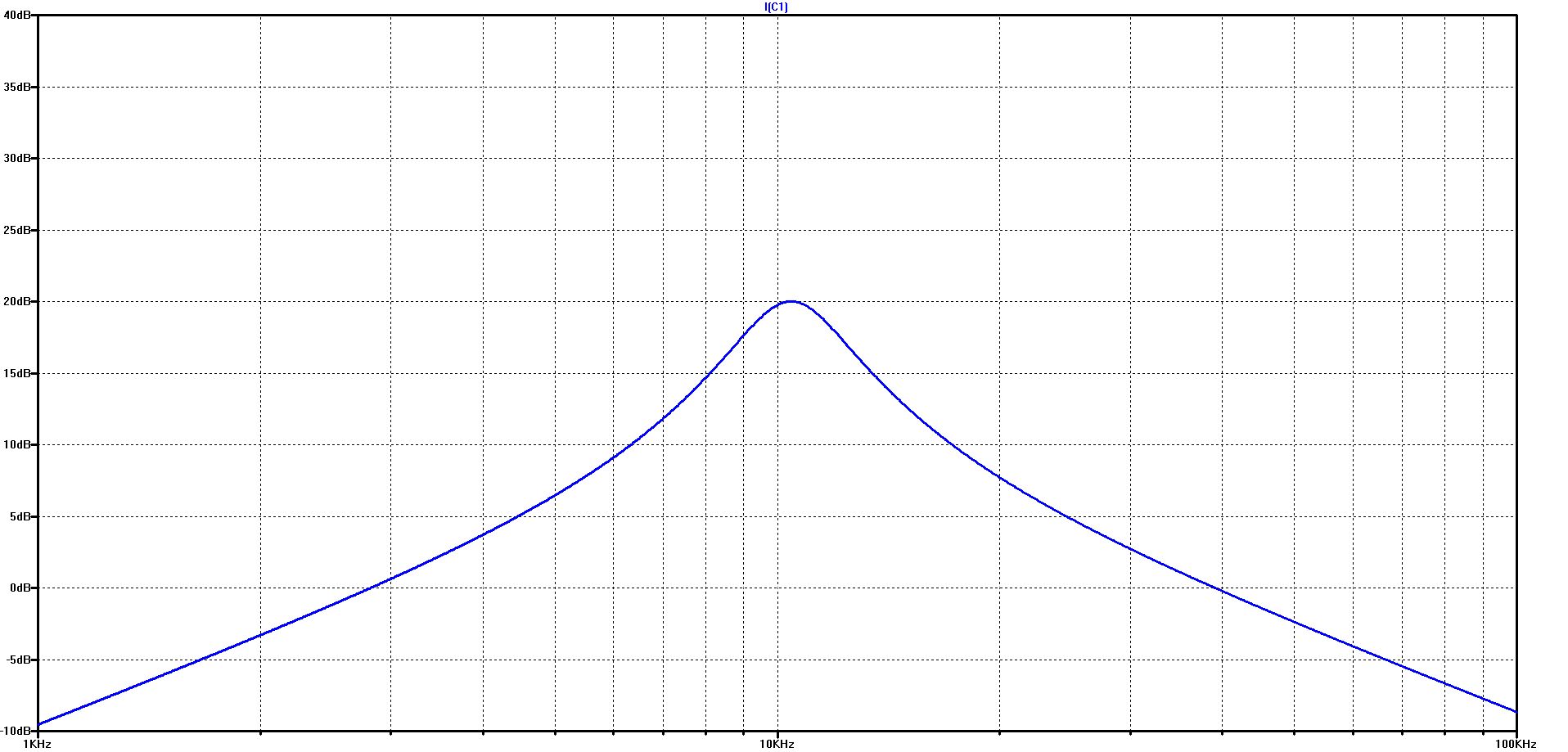
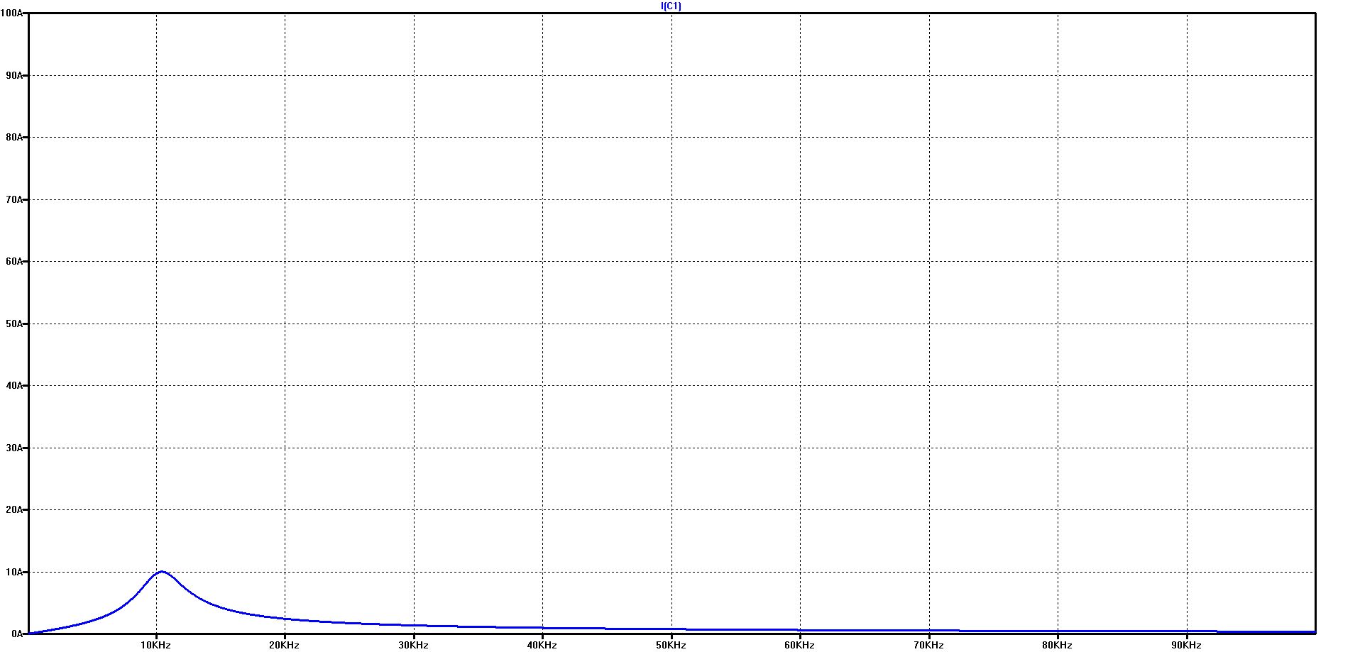
Simulation of the capacitor current with additional simple battery model
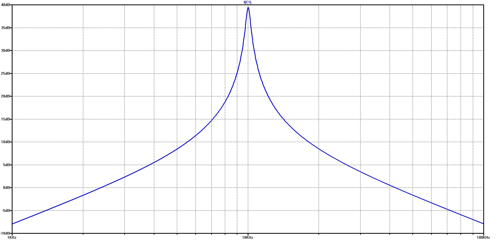
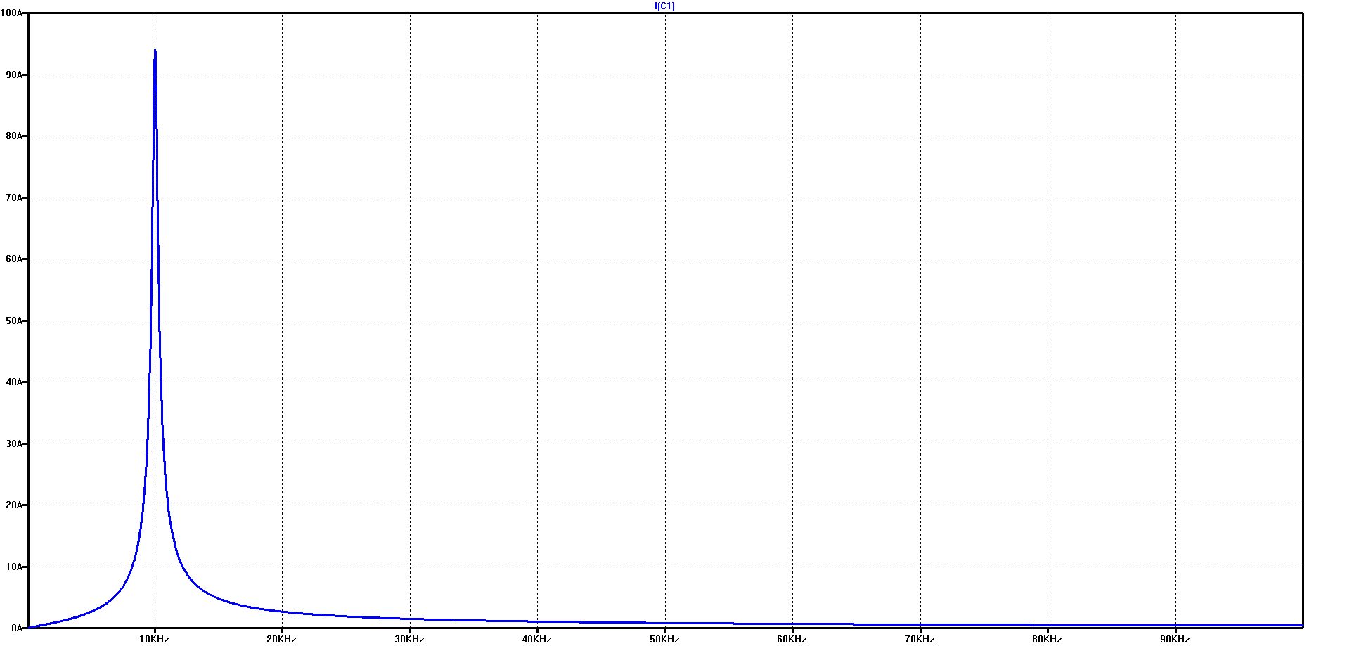
The graph shows how extremely high the current in the DC link capacitor can be exaggerated at the resonant frequency
In our example, a voltage of 1 volt is sufficient to drive a current of more than 90 A through the capacitor at the resonance point
To be noted: all inductors here have a series resistance of 0 ohms
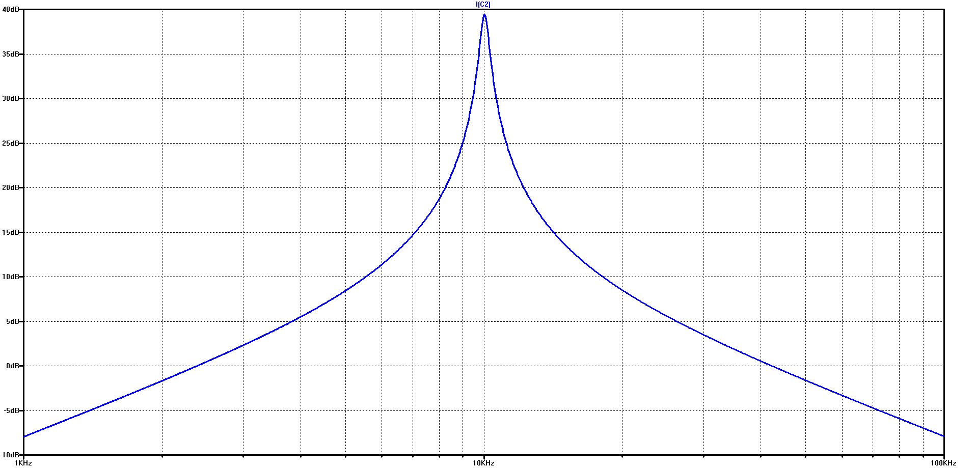
The course of the capacitor current over frequency in the logarithmic diagram on the left and in the linear diagram on the right
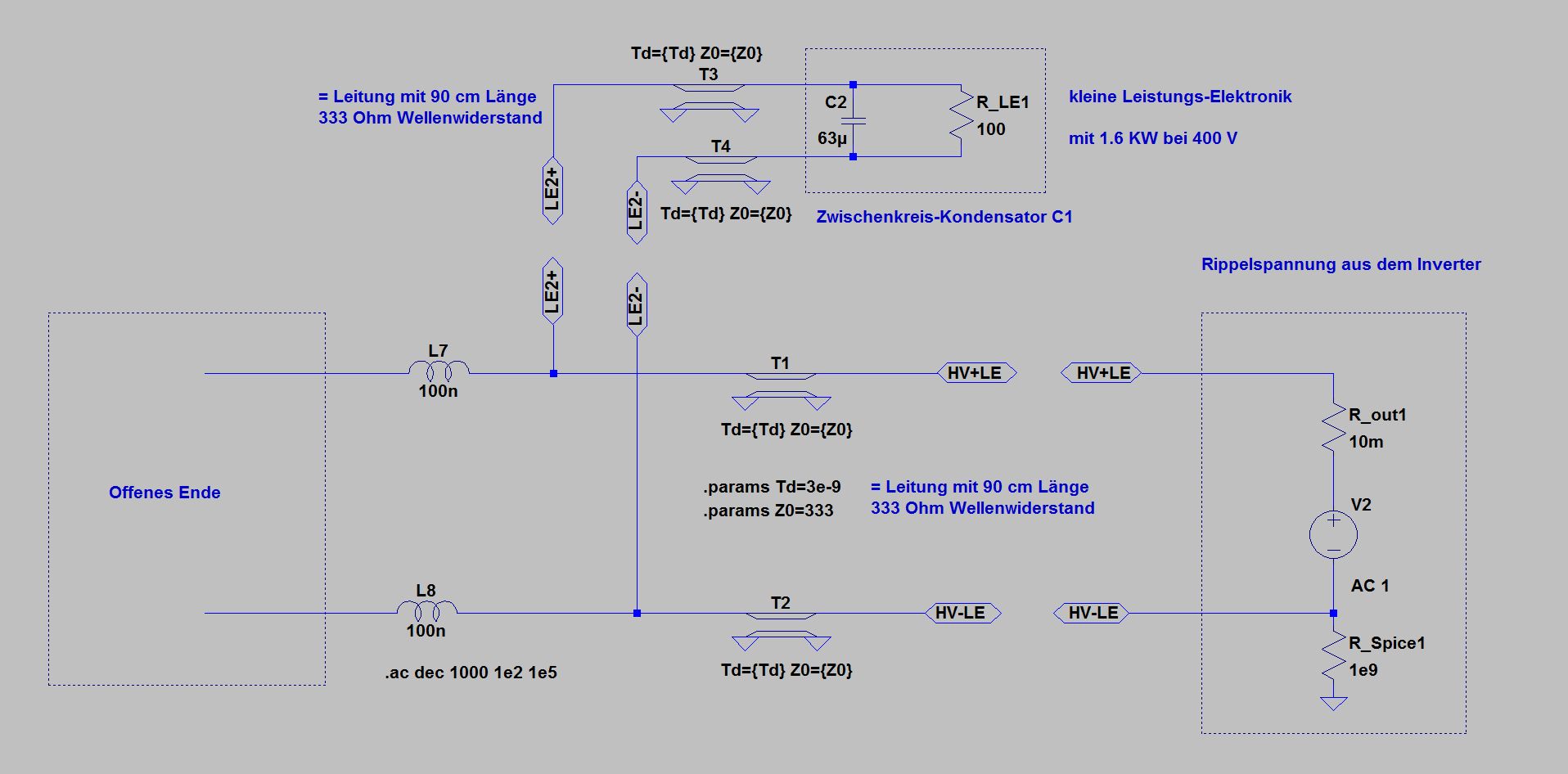
Simulation with lines equivalent to the inductors
Instead of the inductors equivalent lines are used. An inductance of 1 μH corresponds pretty much to a cable with a length of 90 cm and a characteristic impedance of 333 ohms. The length here is the electrical length of the line. The electrical length is extended by the dielectric of the line by root (epsilon r). In typical shielded HV-lines, the mechanical length would be about half, so about 45 cm.
The shielding of a line has a very significant effect on the characteristic impedance and thus the equivalent inductance and the resonance frequency of the connected electronics. This must be taken into account when designing on-board networks
With the equivalent lines, identical current curves result for the simulation with inductances
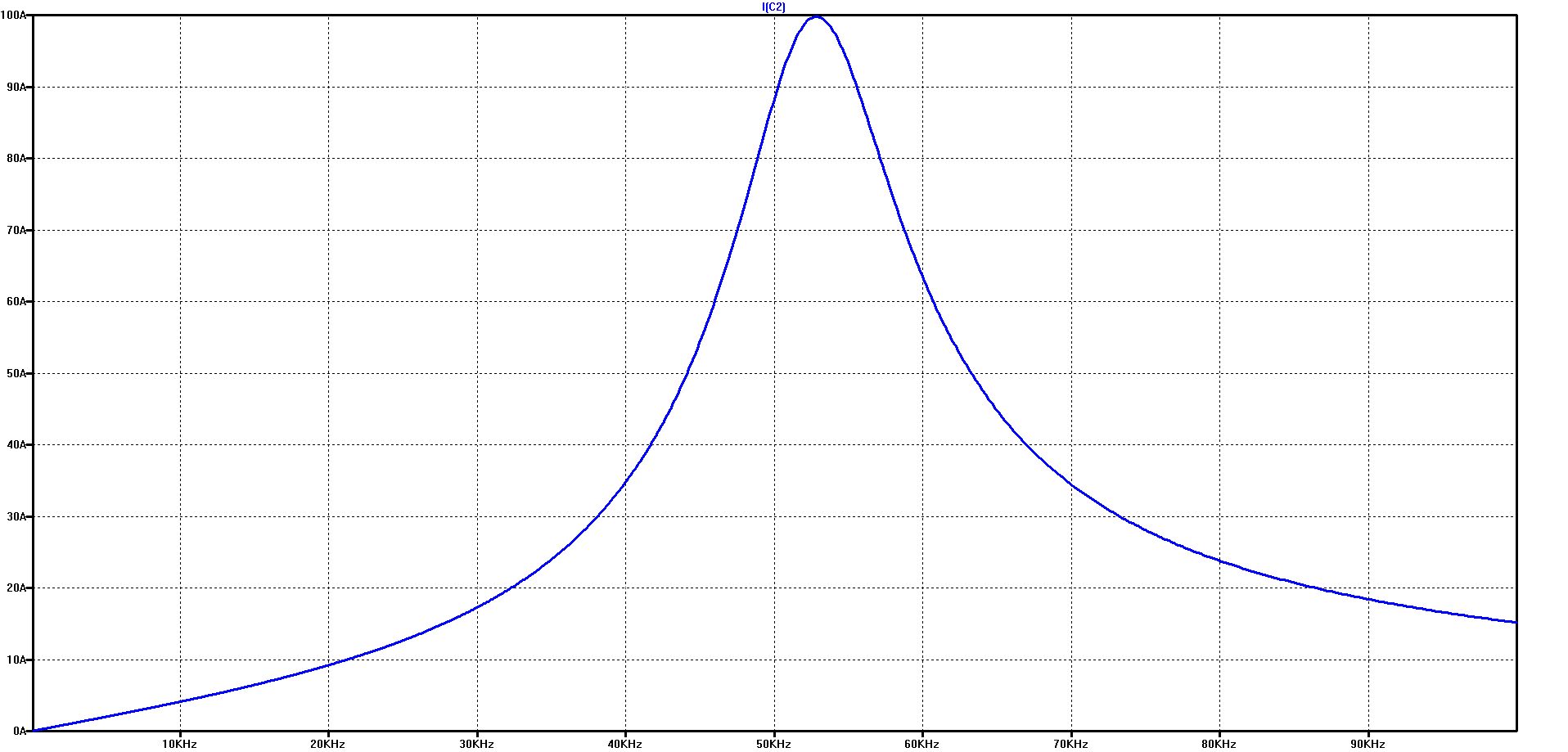
With shielded lines (characteristic impedance 12 ohms), the resonance frequency shifts from 10 kHz to> 50 kHz for the same length
The effect of the battery model results in a slight shift of the resonance frequency and a significant reduction in the maximum current in the resonance point - from over 90 A to about 25 A.
Because of the easier handling and the better clarity, inductances are used instead of lines in the following simulations
As the above examples have shown, there are no significant differences in the considered frequency range
Ripple-Voltage test with artificial network (BNN = AN = LISN)
The artificial network (BNN = AN = LISN) decouples the dampening effect of the battery
All the more important becomes the internal resistance of the test generator, as shown in the following diagrams (of course, the line lengths are different in a real test, but not in our example, to make it easier to compare the effects).


Capacitor current with artificial network (BNN = AN = LISN) at 10 mOhm generator resistance (logarithmic left, linear right)
Capacitor current with artificial network (BNN = AN = LISN) at 100 mOhm generator resistance (logarithmic left, linear right)
With 100 mOhm instead of 10 mOhm output resistance of the generator, the maximum capacitor current is reduced from more than 90 A to about 10 A.
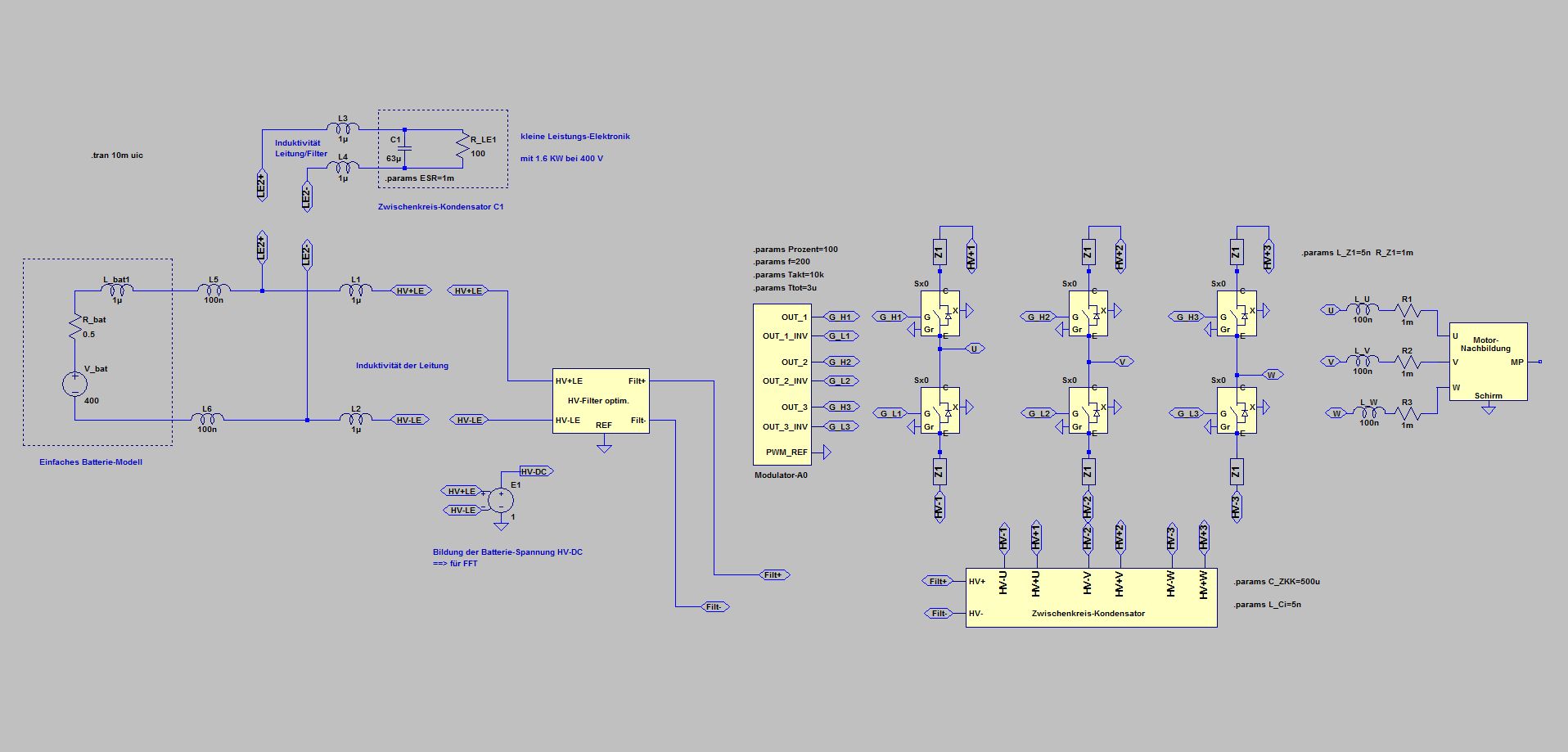
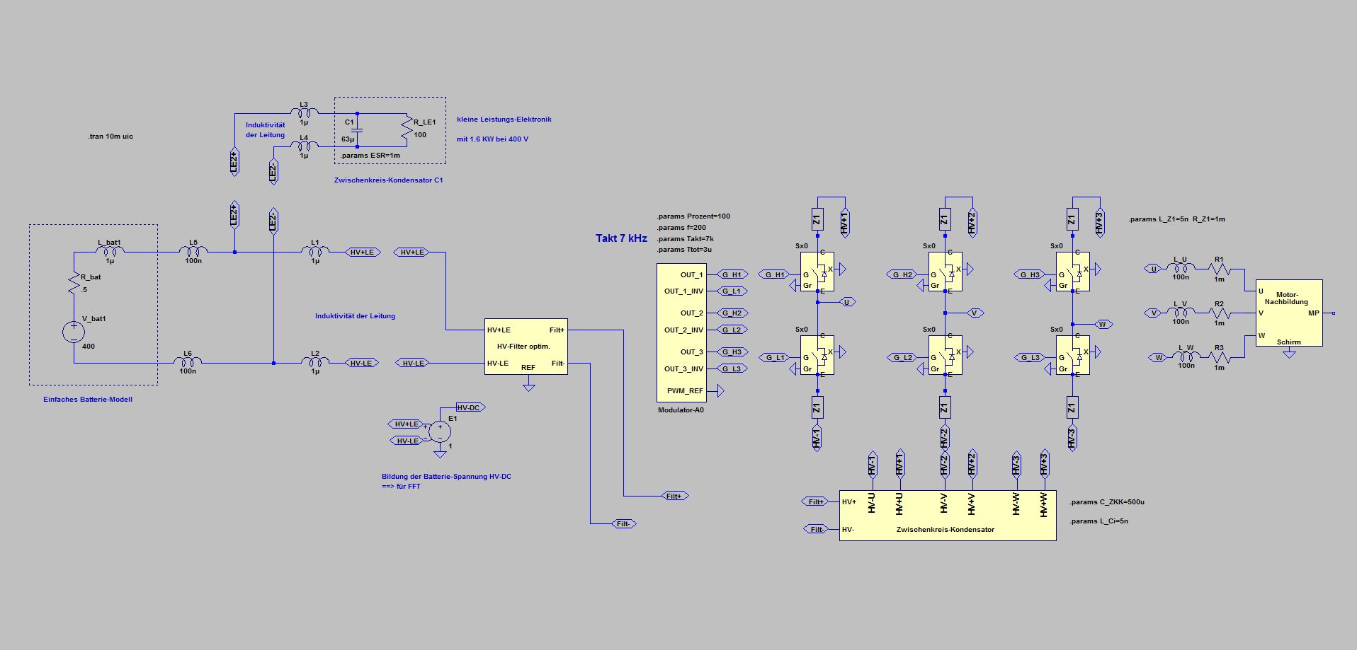
Simulation in time domain: Ripple voltage from the real inverter with 10 kHz clock, with 100% modulation and 200 Hz rotation frequency
L1 to L4 together with C1 in resonance at the clock frequency
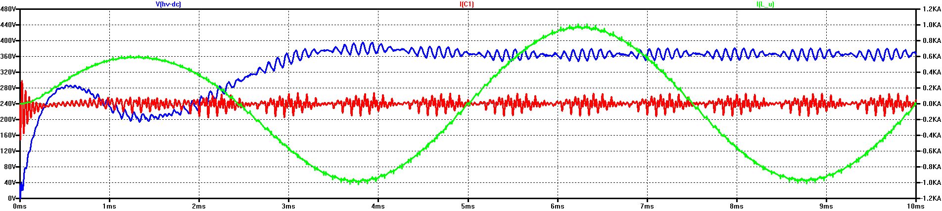
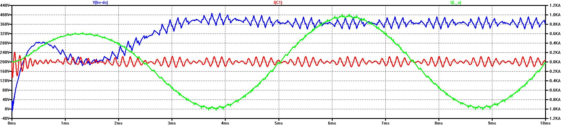
Ripple-Voltage (blue: V(HV-DC)) Ripple-Current through C1 (red: I(C1)) with ESR = 1 mOhm Phase-Current (green: I(L_U))
RMS of I(C1) = 162 A
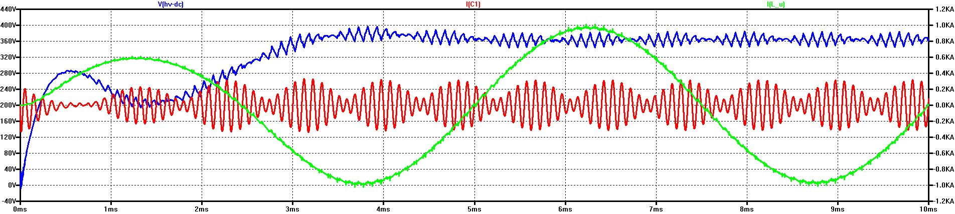
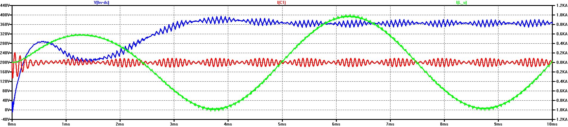
Ripple-Voltage (blue: V(HV-DC)) Ripple-Current through C1 (red: I(C1)) with ESR = 10 mOhm Phase-Current (green: I(L_U))
RMS of I(C1) = 136 A
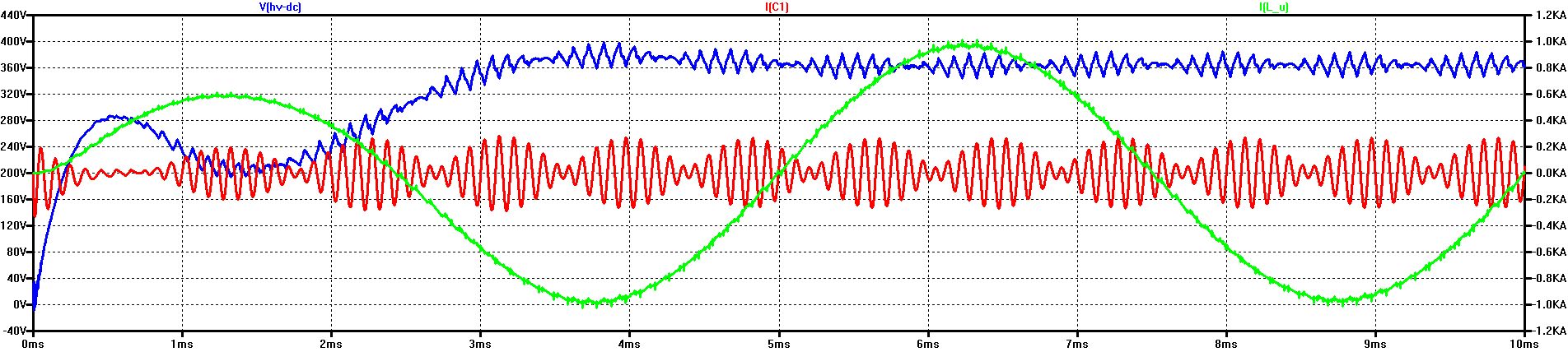
Simulation in time domain: Ripple voltage from the real inverter with 10 kHz clock, with 100% modulation and 200 Hz rotation frequency L1 to L4 100 nH instead of 1 uH not in resonance with C1 at the clock frequency
Ripple-Voltage (blue: V(HV-DC)) Ripple-Current through C1 (red: I(C1)) with ESR = 1 mOhm Phase-Current (green: I(L_U))
RMS of I(C1) = 50 A
As already noted, unshielded lines have a much higher inductance than shielded lines. The transition to the unshielded vehicle electrical system could thus shift the inductance of the lines from a few 100 nH into the range of several micro-Henry and thus the intermediate circuits of smaller power electronics in the resonance range shown here.
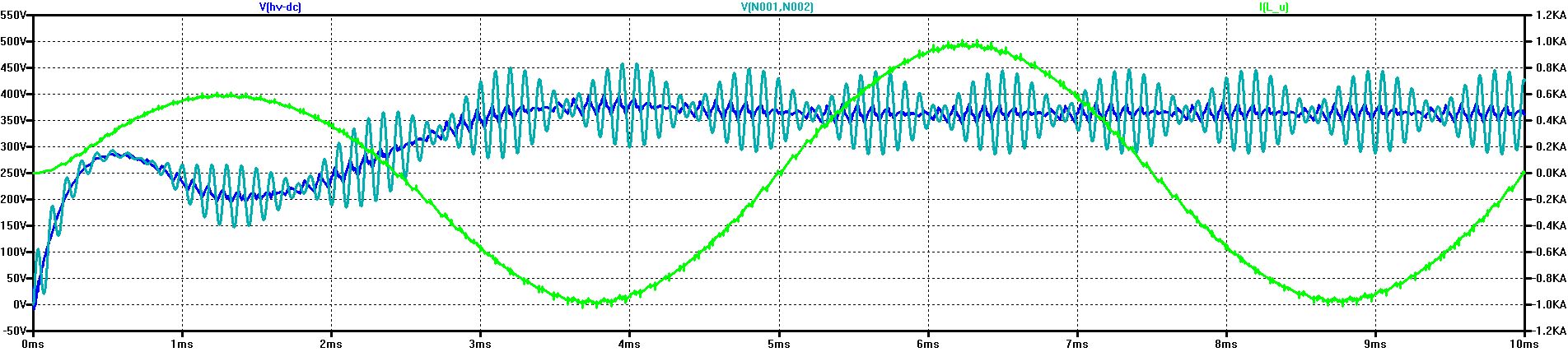
Turquoise: V(N001, N002) Ripple-Voltage at the DC link of LE2 (at C1) in case of resonance with 4 x 1 μH with ESR = 1 mOhm
Maybe also problematic:
The Ripple-Voltage at the DC link of the LE2 is higher by a factor of 4 than at the inverter port, V(HV-DC), 160 V instead of 40 V
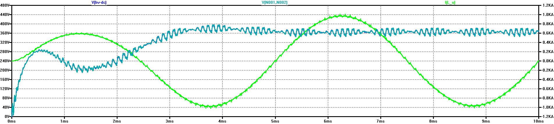
Turquoise: V(N001, N002) Ripple-Voltage at the DC link of LE2 (at C1) not in resonance with 4 x 100 nH with ESR = 1 mOhm
Unproblematic: The ripple voltage at the DC link of the LE2 is only slightly higher than at the inverter port, V(HV-DC)
Cross-check with shifted clock frequency: 7 kHz instead of 10 kHz and then 13 kHz instead of 10 kHz
Clock frequency: 7 kHz RMS of I(C1) = 51 A
Clock frequency: 10 kHz RMS of I(C1) = 162 A
Clock frequency: 13 kHz RMS of I(C1) = 46 A
Analogous to the simulations in the frequency domain, there is also a drastic increase in the simulation in the time domain with complete inverter when the clock is at 10 kHz with a rotation frequency of 200 Hz and the highest spectral lines are at 9.4 and 10.6 kHz - and thus very close to the DC link resonance of the LE2
Even at 7 kHz, the effective current through the DC link capacitor C1 has dropped below one third, although the Ripple-Voltage has increased due to the lower switching frequency
In contrast to the simulations in the frequency domain, the capacitor current approaches never 0, even far away from the resonance.This prevent the numerous secondary lines that exist at any time (see spectrum).
© Ingenieurbüro Lindenberger 8447