

Shielding
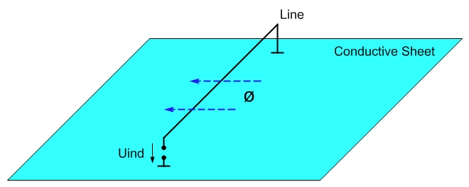
The picture shows a single line that is connected to a conductive sheet (e.g. aluminum sheet) at 2 points.
If an external magnetic field now goes through the surface spanned by the cable and the sheet, a voltage induced in the cable can be measured at any point on the cable if it is separated there (as in the picture at Uind).
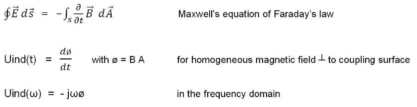
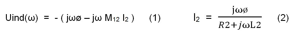
The voltage Uind results from the following formulas:
Principle of Shielding Lines against Alternating Magnetic Fields
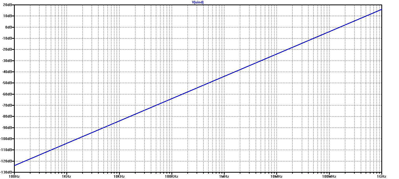
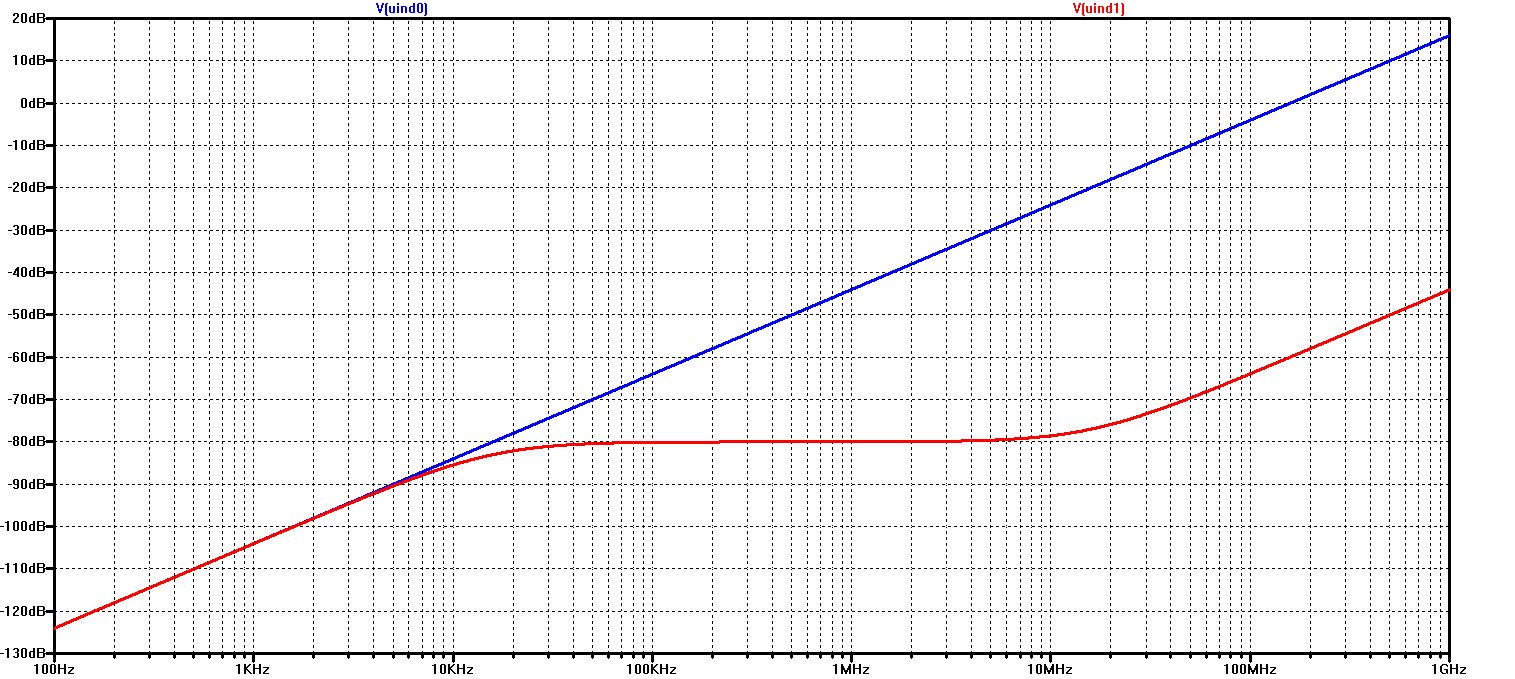
The diagram shows Uind (referred to as V (uind)) as a function of frequency
The values shown are for a magnetic flux of 1 nWb 0 dB corresponds to 1 V -60 dB corresponds to 1 mV
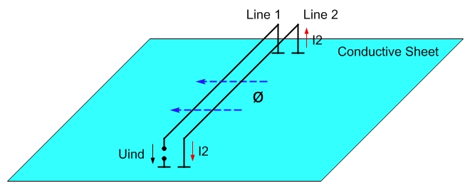
If a short-circuit line (Line 2) is attached close to line 1, as in the picture above, the magnetic flux also flows through the surface of the short-circuit line - and reduces the induced voltage in Line 1.
The magnetic flux through Line 2 causes the current I2, which in turn causes an opposing magnetic field that also acts in Line 1 (mutual inductance):
with
M12 = mutual inductance between Line 1 and Line 2
L2 = inductance of Line 2
R2 = Ohmic resistance of Line 2
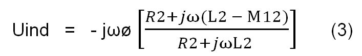
Uind(ω) or simply written Uind can be transformed as shown in (3):
The term in the square brackets can be understood as the reduction factor of the short-circuit line

formula (3) can be represented as follows:
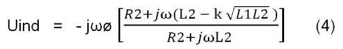
For L1 = L2 = L these simplifications result:

and

if additionally k = 1
From (3) to (6) it follows:
- In order for Uind to be as small as possible, both lines must be coupled as closely as possible
(M12 ≈ L2 if Line 2 is the shielding of Line 1)
- The effectiveness of the shielding is better, the lower the resistance of the shielding and the contact resistance
- The shielding effect goes relatively quickly towards zero in the direction of low frequencies (< 1 kHz)
- To increase the shielding effect, magnetic materials, e.g. Ferrites or nanocrystalline cores can be used -
if the current on the screen is not so high that the cores saturate
Simulation of the Shielding Effect of Cable Shields
Simulation of the shielding effect for 100 mOhm shielding resistance ( = Zt ) with an inductance of 1 uH for Lines 1 and 2 and a coupling factor k of 0.9995
V(uind0) shows the induced voltage in Line 1 without shielding line, V(uind1) shows the induced voltage in Line 1 with shielding line
(Line 2)
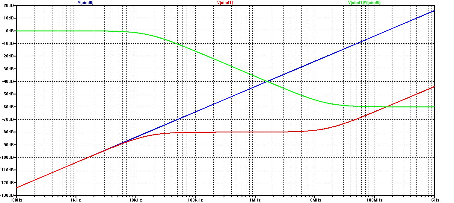
The green trace V(uind1)/V(uind0) shows the shielding attenuation as a function of the frequency
(Zt = 100 mOhm, L1 = L2 = 1 uH and k = 0.9995)
Analogous to the course of the red trace V(uind1), the attenuation rises steadily from about 10 kHz to about 10 MHz - to remain constant above 10 MHz
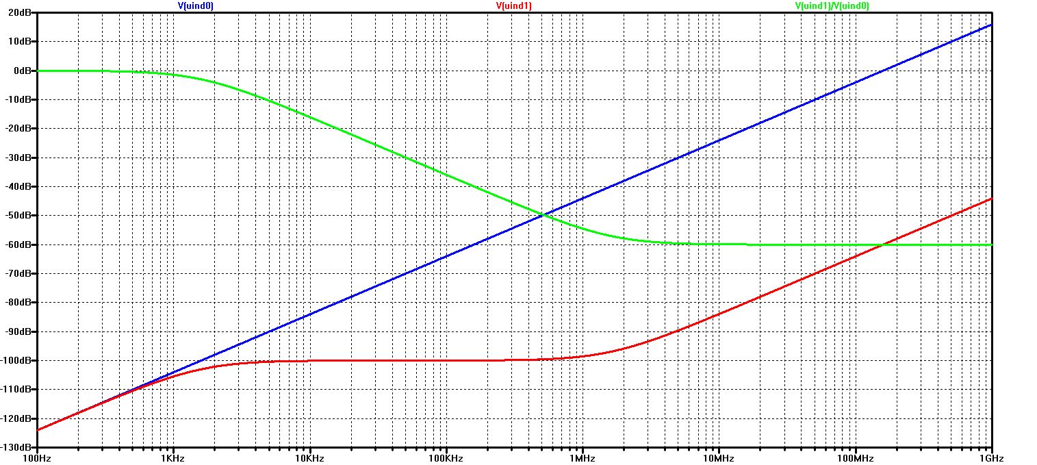
Frequency characteristic for Zt = 10 mOhm (and L1 = L2 = 1 uH and k = 0.9995)
With the shield resistance Zt lower by a factor of 10, the damping effect starts at 1 kHz - but remains limited to 60 dB as before (due to the coupling factor k = 0.9995)
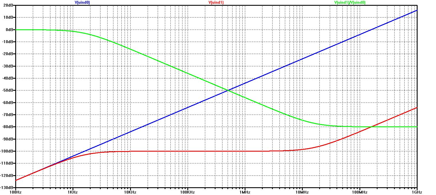
Frequency characteristic for Zt = 10 mOhm and k = 0.99995 (and L1 = L2 = 1 uH)
Only through the improved coupling factor can the maximum shielding attenuation be increased to 80 dB
With regard to real cable shielding, these effects mean:
- For maximum effect at low frequencies, the lowest possible screen resistance Zt is critical, i.e. a lot of copper
- For maximum effect at higher frequencies, the best possible coupling of the shield to the shielded cable is necessary, in addition to a gap-free shield cover as well as a connection without additional inductance - i.e. 360 ° all around - and no pigtails
Annoyed by formulas ? Now it goes on without formulas:
Shielding against Emission of Alternating Magnetic Fields
The shielding against the emission of alternating magnetic fields works in a similar way to the shielding against magnetic fields coupling in from the outside.
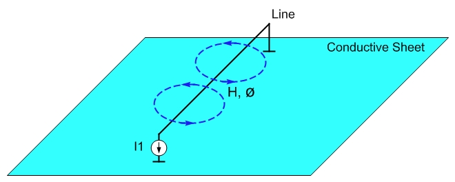
The picture shows a simple line that is connected to a conductive sheet (e.g. made of aluminum) at two points.
At an arbitrary point, the current flow I1 is now fed into this line, which flows back to the other end of the line via the conductive sheet. The line surrounds itself with the magnetic field H - creating a magnetic flux ø, corresponding to L ∙ I1. L is the inductance of the line.
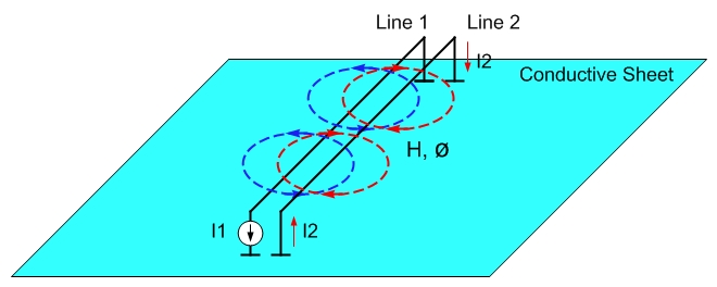
If a short-circuit line (Line 2) is attached close to Line 1, as in the picture above, the magnetic flux also flows through the surface of the short-circuit line - and induces a current flow in Line 2, in the opposite direction to Line 1.
The current I2 in turn generates an opposing magnetic field that compensates for the excitation field of Line 1 - and the better the smaller the resistance in Line 2 - and the better the coupling of Line 1 and Line 2.
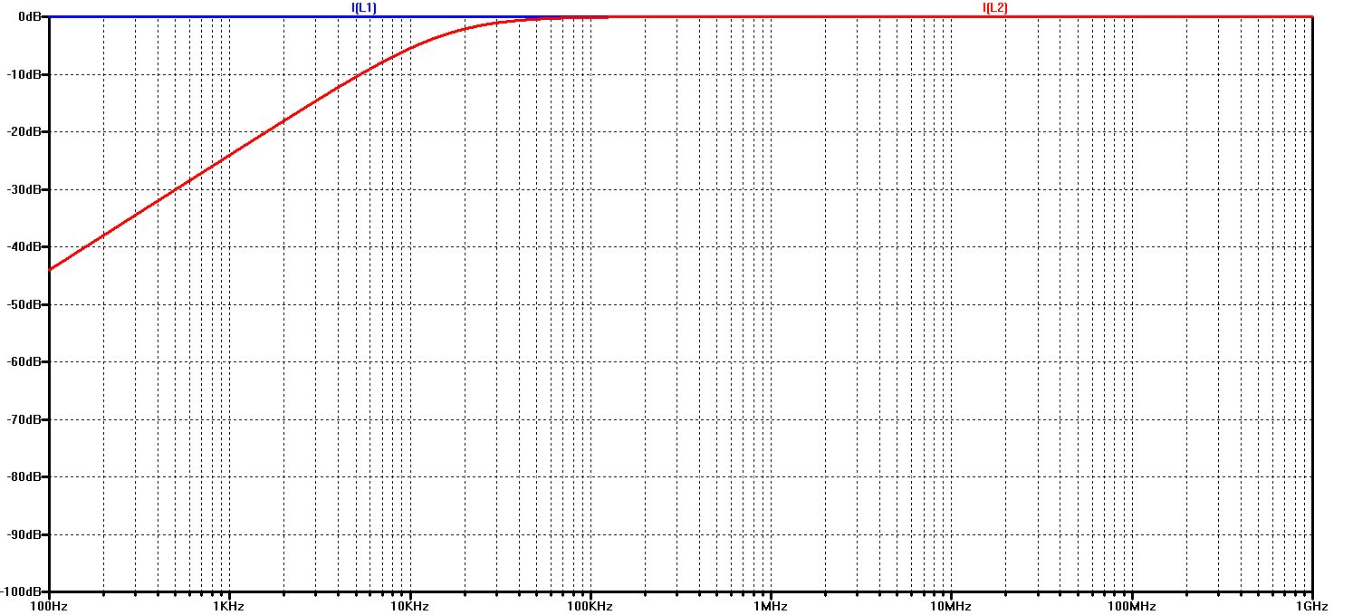
Simulation of the shielding effect for 100 mOhm shielding resistance (= Zt) with an inductance of 1 uH for Lines 1 and 2 and a coupling factor k of 0.999
I(L1) shows the excitation current in Line 1 (here 1 A), I(L2) shows the counter current induced in Line 2
The resulting total current in both lines, relative to the excitation current, is a measure of the shielding attenuation
The green trace I(L1)+I(L2), the total current from both lines, therefore shows the shielding attenuation as a function of the frequency
for Zt = 100 mOhm, L1 = L2 = 1 uH and k = 0.999
Analogous to the adjustment of the counter current I(L2) to the excitation current I(L1), the damping rises steadily from about 10 kHz to about 10 MHz - to remain constant above 10 MHz
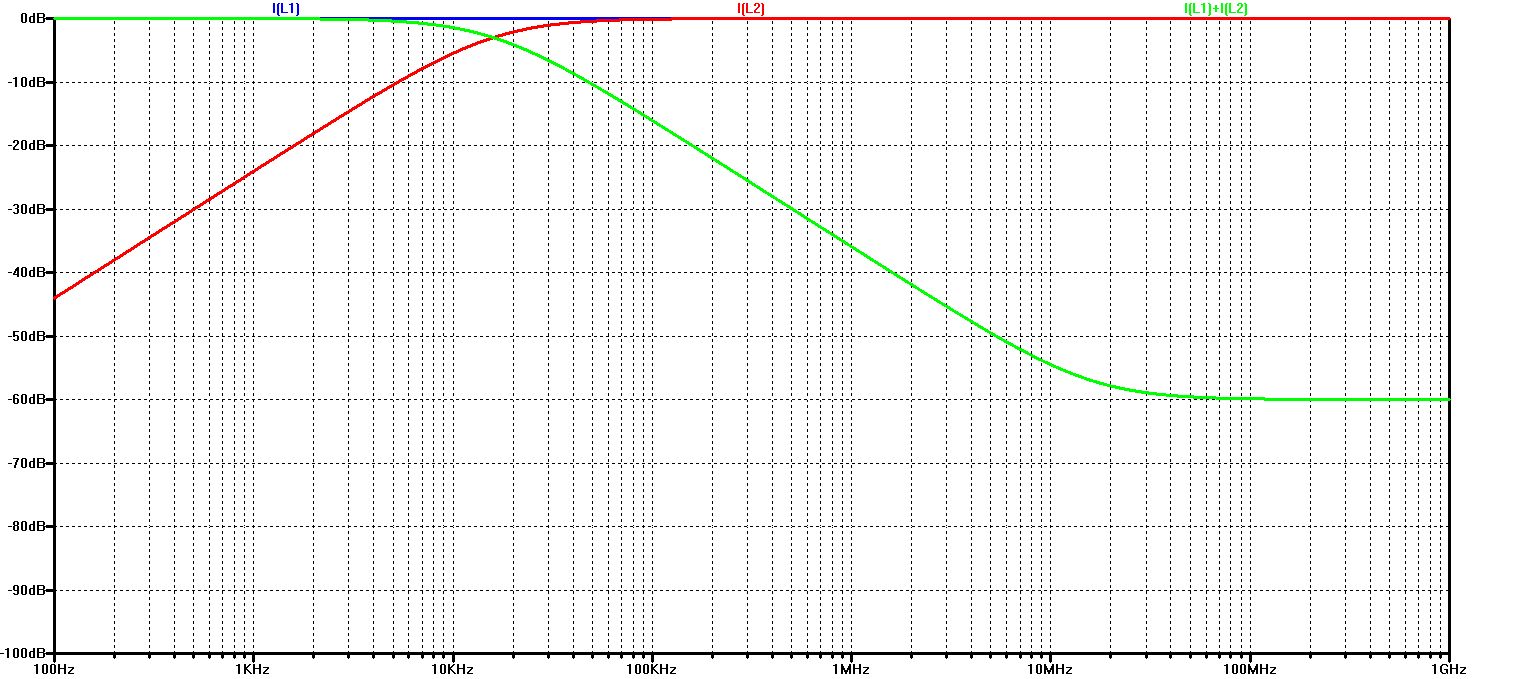
Frequency characteristic for Zt = 10 mOhm (and L1 = L2 = 1 uH and k = 0.999)
With the shield resistance Zt, which is 10 times lower, the damping effect starts at 1 kHz - but remains limited to 60 dB as before (due to the coupling factor k = 0.999)
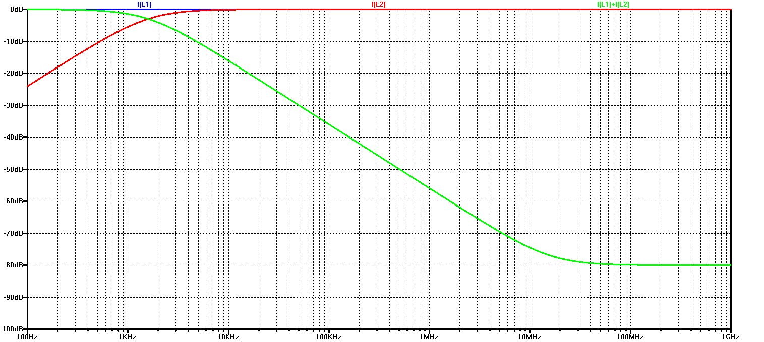
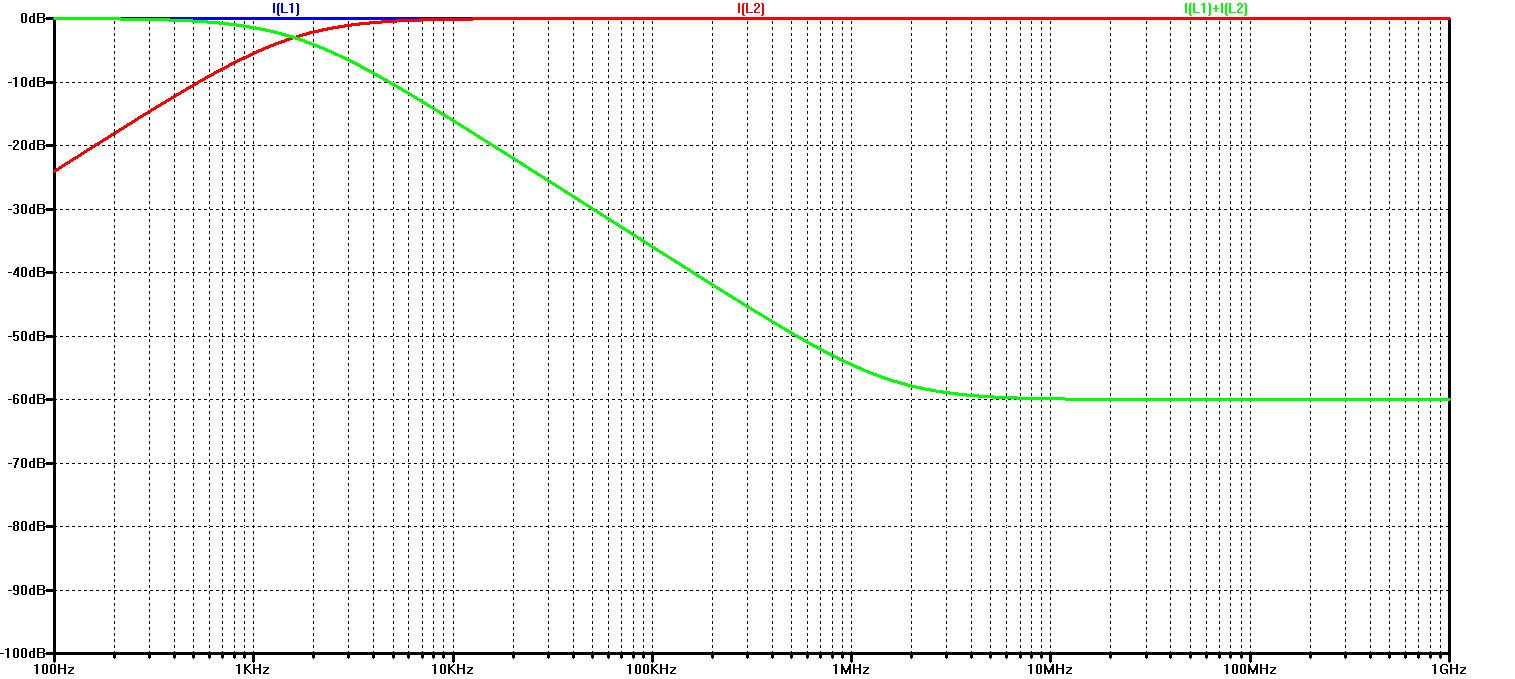
Frequency characteristic for Zt = 10 mOhm and k = 0.9999 (and L1 = L2 = 1 uH)
Only through the improved coupling factor can the maximum shielding attenuation be increased to 80 dB
With regard to real cable shielding, these effects mean:
- For maximum effect at low frequencies, the lowest possible screen resistance Zt is decisive, i.e. a lot of copper
- For maximum effect at higher frequencies, the best possible coupling of the shield to the shielded cable is necessary, in addition to a gap-free shield cover as well as a connection without additional inductance - i.e. 360 ° all around - and no pigtails
The derivations and simulations shown here do not take into account line transformations or line resonances.
They are particularly well suited for the evaluation of line shielding at low frequencies below strong transformation or resonance effects.
Example:
For a 2 m long shield line connected to ground on both ends, the first resonance occurs at 75 MHz, or lambda/2.
No special deviations are to be expected up to 10 MHz, and not too large up to 30 MHz. For shorter or longer lines, increase or decrease these frequencies accordingly.
© Ingenieurbüro Lindenberger 8447